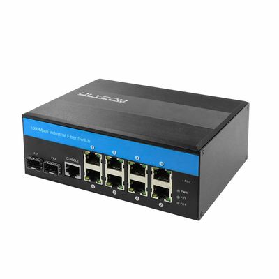
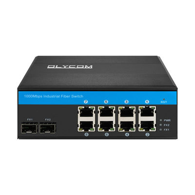
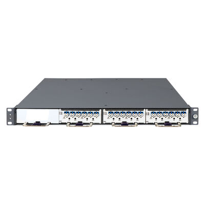
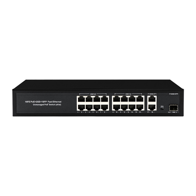
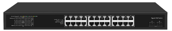
Olycom 24 Port CCTV PoE Switch with 2.5G Fiber uplinks
Product Highlights
- 24*1Gbps PoE ports+2*2.5Gbps SFP ports
- Support IEEE802.3, IEEE802.3u, IEEE802.3x, IEEE802.3ab, IEEE802.3z
- Ethernet Ports support 10/100/1000Mbps self-adaptive
- Support automatic port flipping (Auto MDI/MDIX)
- Adopt a storage and forwarding exchange mechanism
- PoE ports automatically enable PoE watchdog mode in Extend and VLAN modes
- Support loop alarm function
- The panel indicator LEDs will monitor the working status and assist in fault analysis
- Ports 1-2 support HiPoE 60W
- Support PoE priority to be enabled by default, with a priority order of 1-24
Hardware Features
|
Description
|
Specification
|
|
Model
|
OM-2(2)2424-PSE-GE
|
|
Interface
|
24*1Gbps PoE ports
2*2.5Gbps SFP ports
|
|
Port Standard
|
IEEE 802.3: Ethernet Media Access Control (MAC) Protocol
IEEE 802.3i: 10BASE-T Ethernet
IEEE 802.3u: 100BASE-TX Fast Ethernet
IEEE 802.3ab: 1000BASE-T GigabitEthernet
IEEE 802.3z: 1000BASE-X Gigabit Ethernet (Fiber optic)
IEEE 802.3x: Flow Control
|
|
Switching Bandwidth
|
58Gbps
|
|
Packet Forwarding Rate
|
43.15Mpps
|
|
Packet Buffer
|
8.4Mbit
|
|
MAC Address Table
|
16K
|
|
Jumbo Frame
|
12Kbytes
|
|
VLAN
|
VLAN range 1-4094, maximum active VLAN is 31
|
|
Transmission Method
|
Store and Forward
|
|
PoE Standard
|
IEEE802.3af (15.4W)
IEEE802.3at (30W)
|
|
PoE Port Output Voltage
|
DC 44-57V
|
|
PoE Ports
|
Ports 3-24 PoE power output <30W
Ports 1-2 supports HiPoE 60W
|
|
PoE Power Budget
|
280W
|
|
Power Supply
|
AC 100-240V 50/60Hz
DC 52V 5.77A
|
|
Mainboard Power Consumption
|
15.59W
|
|
Structure Information
|
Product Dimensions: 440*204*44mm
Packaging Dimensions: 500*290*85mm
Product Net Weight: 2.84KG
Product Gross Weight: 3.42KG
|
|
Packing Information
|
Carton Dimensions: 520*445*310mm
Packing Quantity: 5PCS
Packing Weight: 18.1KG
|
|
Package Contents
|
Switch 1pcs, Power Cord 1pcs, Manual 1pcs, Certificate of Inspection 1pcs, Rack-mounting kit 1pair
|
|
Fan Quantity
|
0
|
|
Installation
|
Desktop, Rack-mounting
|
|
Surge Protection
|
Port Surge: Common mode 6KV, Differential mode 2KV (Class C)
Electrostatic ESD: Air 8KV, Contact 6KV (Class B)
Power Supply: Common mode 4KV, Differential mode 2KV (Class B)
|
|
Operating Temperature
|
0~40°C
|
|
Storage Temperature
|
-40~70°C
|
|
Operation Humidity
|
10%~90%, non condensing
|
|
Storage Humidity
|
5%~95%, non condensing
|
|
PWR Green LED
|
On: Powered on
Off: Powered off
|
|
Ports 1-24
|
Green LED on: 1Gbps Link normal
Yellow LED on: 10/100Mbps Link normal
Off: Link blocked
Flashing: Data transmitting
Slow Flashing: When a local or cross-product loop is detected, the port will flash slowly
|
|
PoE Yellow LED
|
On: PoE powered on
Off: PoE powered off
|
|
Ports 25-26
|
Green LED on: 2.5Gbps Link normal
Yellow LED on: 1Gbps Link normal
Off: Link blocked
Flashing: Data transmitting
|
|
PoE Max Green LED
|
Off: Indicate that the PoE power usage is less than 90%
Flashing(Once per second): Indicate that the PoE power usage of 90% ≤ P ≤ 95%
On: Indicate that the PoE power is used at 95%<P<100%
|
|
VLAN/Default/Extend Modes Buttons
|
VLAN: VLAN mode, ports 1-22 are isolated from each other, communicating with ports 25-26, and automatically activate the PoE watchdog mode
Default: Normal mode, all ports can communicate with each other, transmission distance is within 100 meters, transmission rate is 10/100//1000Mbps adaptive(PoE Watchdog off)
Extend: Extend mode, when the PoE port is in Extend mode, ports 17-24 force 10Mbps to extend the transmission distance to 250meters, and automatically activate the PoE watchdog mode
|
Mounting Diagram

QC Framework
1. Quality Standards and Compliance
Industrial optical transmission equipment is designed for mission-critical communication environments where long-distance stability, electromagnetic resistance, and continuous operation are essential. To ensure reliable performance in harsh deployment conditions, all products are developed and manufactured under a comprehensive quality management system aligned with international industry standards.
The manufacturing and verification process complies with:
* ISO9001 quality management systems
* CE and FCC certification requirements
* RoHS environmental compliance
* IEC 61753 fiber optic device performance standards
* ITU-T G.694.1 wavelength specifications for optical transmission systems
In addition to international compliance standards, products are validated according to industrial networking and long-distance fiber communication requirements commonly found in:
* Industrial automation systems
* Power utility communication networks
* Transportation infrastructure
* Intelligent traffic systems
* Oil & gas facilities
* Railway communication networks
* Security and surveillance systems
Special attention is given to optical transmission reliability, anti-interference capability, surge protection, and stable communication performance under complex industrial operating environments.
2. Quality Control Process
A strict end-to-end quality control framework is implemented throughout material sourcing, optical assembly, transmission validation, and final delivery inspection.
2.1 Incoming Material Inspection
All critical optical and electronic components are verified before entering the production line.
Inspection targets include:
* Optical fibers and patch components
* Fiber connectors and adapters
* Optical transmission chips
* Industrial-grade power modules
* Surge and lightning protection devices
* PCB assemblies and communication interfaces
* Metal housings and thermal components
Incoming inspection ensures component consistency, transmission stability, and long-term reliability under industrial operating conditions.
2.2 Production Assembly and Optical Coupling Control
During manufacturing, strict assembly procedures are implemented to maintain stable optical signal transmission and mechanical integrity.
Key control points include:
* Optical path alignment verification
* Fiber coupling precision inspection
* Connector insertion consistency
* PCB soldering inspection
* Shielding and grounding verification
* Thermal dissipation structure confirmation
Production personnel and automated inspection systems jointly verify assembly quality to reduce signal loss and improve transmission stability.
2.3 Functional and Transmission Performance Verification
Each unit undergoes comprehensive transmission and communication testing before shipment.
Testing procedures include:
* Optical transmission index verification
* Relay transmission functionality testing
* Packet forwarding stability testing
* Optical attenuation validation
* Link integrity verification
* Fiber communication continuity testing
* Redundant transmission path verification
* Ethernet and industrial protocol communication checks
Products are tested under simulated network loads to ensure stable long-distance optical communication performance.
2.4 Protection and Reliability Testing
Industrial optical transmission equipment must operate reliably under electrically noisy and environmentally demanding conditions.
To ensure field reliability, products undergo:
* Surge protection testing
* ESD immunity testing
* Electromagnetic interference resistance verification
* Power fluctuation tolerance testing
* Continuous operation stress testing
* Thermal cycling and high/low temperature operation tests
These procedures help validate communication stability during real-world industrial deployment scenarios.
2.5 Aging and Final Inspection
Before shipment, all equipment is subjected to extended aging and regression testing.
This process includes:
* Long-time uninterrupted operation testing
* Stability monitoring during thermal stress
* Full-function regression testing
* Optical signal consistency checks
* Port and interface verification
* Labeling and serial number inspection
Only products that successfully pass all validation stages are approved for delivery.
3. Reliability and Performance Test Items
To ensure stable deployment in industrial fiber communication environments, products are tested across multiple optical and environmental parameters.
Core verification items include:
* Optical insertion loss
* Dispersion tolerance
* Long-distance transmission capability
* Optical relay transmission performance
* ESD resistance capability
* Lightning and surge protection performance
* Communication stability under electromagnetic interference
* Wide temperature adaptability (-40°C to 75°C)
These tests help verify both optical transmission quality and long-term hardware durability.
4. Professional Test Equipment
Advanced optical and environmental testing equipment is utilized throughout the QC process to ensure precise validation and repeatable performance measurement.
Main testing instruments include:
* Optical Time-Domain Reflectometers (OTDR)
* Fiber optic loss testers
* Optical power meters
* ESD simulators
* Surge and lightning protection test systems
* Environmental temperature chambers
* Industrial communication analyzers
* Long-duration aging racks
These tools enable accurate simulation of real-world deployment environments and help ensure stable optical communication performance in industrial applications.
5. Traceability and Quality Management System
A complete traceability system is implemented for all industrial optical transmission products.
Each device is associated with:
* Production batch information
* Optical path test records
* Aging and reliability test data
* Component sourcing records
* Supplier quality documentation
* Firmware and configuration history
* Final inspection reports
This quality management system enables efficient problem tracing, long-term lifecycle support, and continuous production optimization.
The traceability framework is particularly important for industrial and infrastructure projects where operational continuity and maintenance visibility are critical.
6. Continuous Improvement and Reliability Optimization
Quality improvement is continuously driven through production analysis, field feedback, and long-term deployment data collection.
Continuous optimization activities include:
* Optical transmission stability analysis
* On-site fault simulation and reproduction
* Anti-interference structure enhancement
* Surge and lightning protection optimization
* Thermal management improvement
* Supplier quality performance evaluation
* Manufacturing process refinement
By continuously improving product design, testing standards, and production consistency, the overall reliability and stability of industrial optical transmission systems can be further enhanced.
The ultimate objective is to provide highly reliable optical communication equipment capable of maintaining stable long-distance transmission performance in complex industrial and outdoor environments while minimizing communication interruption and field failure rates.

 Your message must be between 20-3,000 characters!