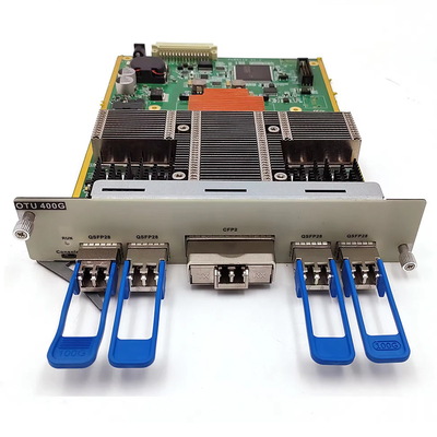
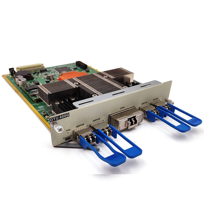
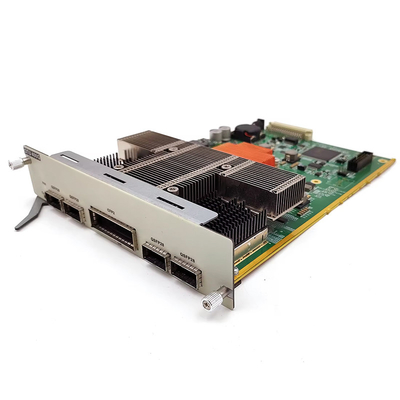
Olycom 400G Muxponder CFP 2 DWDM Optical Transport Unit
Introduction
Product Parameters
Function | Description |
Interface |
1. Client-side interfaces: 4, pluggable based on QSFP28 2. Line side interface: 1, based on CFP2 pluggable, coherent PDM-QPSK |
Line mode | Support transparent transmission of 1 400G service, which can convert 4 channels of 100G service optical signals on the client side into 1 channel of 400G rate DWDM standard wavelength optical signals |
Repeater mode | Support 400G wavelength electrical relay |
Support business type |
100GE OTU4 |
WDM technology | Support DWDM: C-band 50GHz 96 waves tunable |
FEC technology | Support SDFEC |
Number of occupied slots | Support OM3800 full series chassis, occupying 2 slots, (1U) |
Network management function |
l Support real-time monitoring of port working status, including: transmit optical power, receive optical power, temperature, etc. l Support port loopback function and port shutdown function |
Max power consumption | 50W (including optical module) |
MTBF | >100,000 hours |
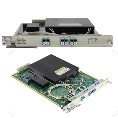
Product Interface
Item | Interface | Description |
CFP2 interface | Tx | Module output optical interface |
Rx | Module input optical interface | |
QSFP28interface | QSFP28 | Module input and output optical interface |
Interface | Item | Description |
RUN | OTU card operation indicator |
On, OTU operation is normal Off, OTU operation failure |
QR1 | Branch 1 module side receiving light indicator |
On, light receiving is normal Off, light receiving is abnormal |
QR2 | Branch 2 module side receiving light indicator |
On, light receiving is normal Off, light receiving is abnormal |
QR3 | Branch 3 module side light receiving indicator |
On, light receiving is normal Off, light receiving is abnormal |
QR4 | Branch 4 module side light receiving indicator |
On, light receiving is normal Off, light receiving is abnormal |
CR | Line-side module light receiving indicator |
On, light receiving is normal Off, light receiving is abnormal |
Diagram
OTU card management interface
OTU Card Setup
1. Device receiving power alarm threshold setting
The receiving power alarm threshold of the optical module can be set through the network management. When the receiving power is lower than the threshold, the device will prompt an alarm and notify the maintenance personnel to pay attention without affecting the business
2. ALS mode setting
The ALS function can be set through the network management system. When the ALS function is enabled, the optical module itself cannot receive light, and the side optical module itself does not emit light.