Understanding the Differences, Use Cases, and Why Industrial Networks Need Both
In industrial Ethernet networks, high availability is not an optional feature but a fundamental design requirement.
Power instability, harsh environments, and long-term unattended operation make network resilience a top priority in sectors such as power utilities, rail transit, oil & gas, manufacturing, and intelligent transportation systems (ITS).
Two protection mechanisms are often mentioned together in industrial network designs: Fiber Bypass power-off protection and ERPS (Ethernet Ring Protection Switching, ITU-T G.8032).
Although both aim to improve network reliability, they operate at completely different layers, solve different problems, and are frequently misunderstood as interchangeable.
This article explains what Fiber Bypass and ERPS actually do, how they differ, and why a truly industrial-grade network design often requires both.
1. What Is Fiber Bypass Power-Off Protection?
Fiber Bypass Switch protection is a hardware-level mechanism designed to ensure optical link continuity when a network device loses power or becomes non-operational.

1.1 The Problem It Solves
In many industrial deployments, devices such as:
are installed inline on fiber links.
Under normal conditions, optical signals pass through the device’s optical transceivers.
However, if the device:
- Loses power
- Experiences hardware failure
- Crashes or hangs at the CPU level
the optical path is physically broken, causing a complete link outage.
Fiber Bypass addresses this exact scenario: a device failure should not break the physical fiber link.
1.2 How Fiber Bypass Works
Fiber Optic Bypass operates at Layer 0 / Layer 1 (physical layer), independent of any software or protocol.
When the device is powered on:
Optical signals pass through the device normally.
When power is lost:
A mechanical optical switch or relay (usually passive)
Automatically connects the incoming and outgoing fiber pairs directly.
This creates a physical optical loop-through, allowing light to pass even though the device is completely offline.
Key characteristics:
- No CPU involvement
- No configuration required
- No protocol dependency
- Immediate activation upon power loss (milliseconds)
Fiber Bypass is often described as a “last-line hardware safeguard.”
1.3 Key Characteristics of Fiber Bypass
Operates at physical layer (L0/L1)
Works even when the device is fully powered off
Protects against device-level failures
Does not perform path selection or topology management
Does not prevent Ethernet loops
2. What Is ERPS (Ethernet Ring Protection Switching)?
ERPS is a Layer 2 protocol defined by ITU-T G.8032, designed to protect Ethernet ring topologies against link failures while preventing broadcast storms.
2.1 The Problem It Solves
Ethernet rings provide natural redundancy, but they also create loops. Without protection, loops cause:
- Broadcast storms
- MAC table instability
- Network collapse
- ERPS allows Ethernet networks to use ring topologies safely by:
- Blocking one link under normal conditions
- Rapidly switching paths when a failure occurs
2.2 How ERPS Works
In an ERPS ring: one link is logically blocked to prevent loops, control messages monitor link health
When a link failure is detected: the blocked port is unblocked, traffic is redirected through the alternate path
Typical convergence time: less than 50 ms, depending on implementation and ring size
ERPS relies on:
- Active switching hardware
- Operational CPU and firmware
- Correct protocol configuration
2.3 Key Characteristics of ERPS
Operates at Layer 2
Requires powered-on, functioning devices
Protects against link failures, not device power loss
Provides fast path re-convergence
Prevents Ethernet loops and broadcast storms
3. Core Differences at a Glance
|
Aspect
|
Fiber Bypass Power-Off Protection
|
ERPS Ring Protection
|
|
Layer
|
L0 / L1 (Physical)
|
L2 (Data Link)
|
|
Purpose
|
Maintain fiber continuity on device failure
|
Recover from link failures
|
|
Dependency on device power
|
None
|
Full
|
|
Configuration required
|
No
|
Yes
|
|
Reaction time
|
Immediate on power loss
|
< 50 ms
|
|
Loop prevention
|
No
|
Yes
|
|
Path optimization
|
No
|
Yes
|
4. A Critical Misconception
A common misconception in industrial networking is: “ERPS can handle device power failures.”
This is incorrect.
If a fiber switch in an ERPS ring loses power: its optical ports go dark
The physical fiber ring is broken, ERPS cannot exchange control messages
In this case, ERPS alone cannot restore connectivity because the physical link no longer exists.
5. Why Fiber Bypass and ERPS Are Complementary?
A robust industrial network design treats Fiber Bypass and ERPS as complementary, not competing technologies.
Fiber Bypass ensures that the physical fiber ring remains intact during device power loss.
ERPS ensures that logical topology convergence and loop-free forwarding.
When used together:
A device loses power, fiber bypass module maintains optical continuity
ERPS detects topology change and traffic is rerouted correctly
This layered protection approach ensures both physical continuity and logical stability.
6. Typical Industrial Use Cases
Fiber Bypass is essential when:
Devices are deployed inline on critical fiber paths
Power instability is expected
Security appliances must not become single points of failure
ERPS is essential when:
Ethernet rings are used for redundancy
Fast recovery from fiber cuts is required
Layer-2 stability is critical
Best Practice: Industrial-grade networks use Fiber Bypass for hardware-level fail-safe protection and ERPS for protocol-level self-healing.
7. Engineering-Level Conclusion
Fiber Bypass power-off protection and ERPS ring protection serve fundamentally different roles:
Fiber Bypass protects the network from dead devices
ERPS protects the network from broken links
One ensures light keeps flowing when hardware fails; the other ensures traffic flows correctly when topology changes.
For mission-critical industrial Ethernet networks, choosing between them is not a design decision.
Using both is.
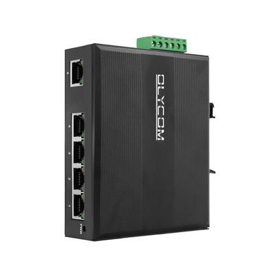
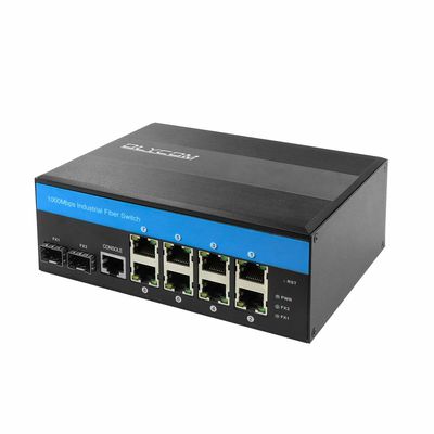
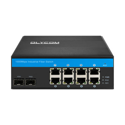
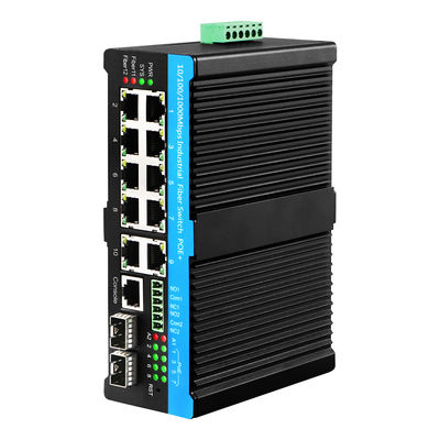
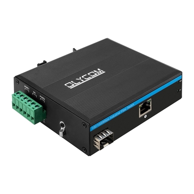
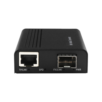
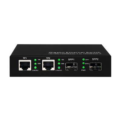
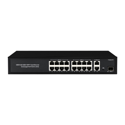
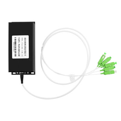
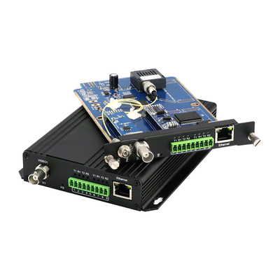
8. What Olycom Can Offer
As an OEM manufacturer, Olycom has been delivering good-quality optical fiber bypass and ERPS solutions.
We integrate an optic bypass unit in a manageable LAN switch to fully fulfill the protection tasks.
| OM-FBS-22-SSC |
2*2B(4*SC) input, single mode simplex SC connector
DC12V/DC24V/DC48V input
|
| OM-FBS-22-SLC |
D2*2B(4*LC) input, single mode Duplex LC connector
DC12V/DC24V/DC48V input
|
| OM-FBS-22-MLC |
D2*2B(4*LC) input, Multi mode Duplex LC connector
DC12V/DC24V/DC48V input
|
| OM-FBS-44-SSC |
D2*2B(8*SC) input, single mode simplex SC connector
DC12V/DC24V/DC48V input
|
| OM-FBS-44-SLC |
D4*4B(8*LC) input, single mode Duplex LC connector
DC12V/DC24V/DC48V input
|
| OM-FBS-44-MLC |
D4*4B(8*LC) input, Multi mode Duplex LC connector
C12V/DC24V/DC48V input
|
Please contact us if you have any projects available, we are here to help.

 Your message must be between 20-3,000 characters!