Preface
In mission-critical industrial and data center networks, high availability and reliability are paramount.
Two important technologies often used together to achieve this are dual power input (AC+DC) and Fiber bypass modules.
Let’s break down how these technologies work together to create resilient infrastructures.
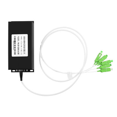
1. What is an Optical Bypass Switch?
A bypass optic switch is designed to maintain uninterrupted network connectivity, even if an in-line device (such as a firewall, IPS/IDS, or UTM) fails or loses power.
It acts as a safeguard:
Normal operation: Traffic flows through the in-line device.
Failure or power loss: The bypass module automatically switches to a fail-open mode, physically bridging the link and allowing traffic to flow uninterrupted.

Typical applications:
- Data center edge networks
- Industrial OT (Operational Technology) systems
- Financial or government networks requiring zero downtime
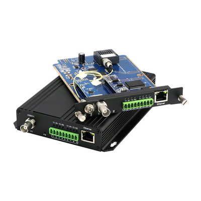
2. Why AC+DC Dual Power Inputs?
Some networking devices (Ethernet switches, firewalls, bypass modules) are built with dual power input options:
AC Power: Usually from mains supply or UPS.
DC Power: Commonly -48V DC, standard in Telecom and carrier environments.
By supporting both AC and DC simultaneously, equipment gains power redundancy:
If AC power fails, the system seamlessly continues running on DC.
If DC power fails, the system continues on AC.
Only if both AC and DC fail, the device truly loses power.
This design greatly increases reliability in environments where uptime is critical.
3. How AC+DC Power and Fiber Optic Bypass Work Together
When a switch and its bypass module are both connected to AC+DC power:
3.1: Normal (AC + DC available)
Switch runs normally.
Bypass module stays active, forwarding traffic through the switch.
3.2: AC fails, DC remains
Switch continues operating on DC.
Bypass module also runs on DC.
Traffic is unaffected, still processed by the switch.
3.3: Both AC and DC fail
Switch loses power completely.
Bypass module also powers off.
The module’s mechanical relay activates, physically shorting the link.
Traffic bypasses the switch entirely, ensuring uninterrupted connectivity.
This creates a two-layer protection model:
First layer: Redundant AC+DC input keeps devices powered during single power failures.
Second layer: Bypass ensures traffic continuity if the device itself fails due to total power loss.
4. Typical Topology
[Core Switch] ---- [Bypass Module] ---- [Firewall/IPS] ---- [Router]
|
+--- AC Power
+--- DC Power
In this setup:
The bypass module and firewall share the same AC+DC sources.
If AC fails → DC ensures continuity.
If both fail → bypass ensures traffic flow.
5. Conclusion
Bypass modules, combined with AC+DC dual power input, deliver a highly resilient network design.
This dual-layer protection ensures:
- Uninterrupted traffic flow even during device or power failures.
- Flexible deployment in AC-only, DC-only, or AC+DC hybrid environments.
- Maximum reliability through combined power redundancy and bypass protection.

 Your message must be between 20-3,000 characters!